- Sign In
- |
- Sign Up
- |
- My Quote (0)
- |
- CART (0)
Provide high-performance triggers and transparent color-coded decode overlays, protocol tables, and search capabilities to the T3DSO2000A series oscilloscopes.
Provide high-performance triggers and transparent color-coded decode overlays, protocol tables, and search capabilities to the T3DSO2000A series oscilloscopes.
Discontinued!
This product has been discontinued and is no longer available. There are no replacement options.
We can help you find what you need:
Features
Supports
Physical layer measurements
Extensive triggering capabilities ("T")
Triggering on the complex FlexRay protocol is made easy. Set up a simple TSS (Start) symbol trigger with a single button press or trigger on any part of a FlexRay frame including ID, Cycle Count, Cycle Repetition Factor, and Frame Qualifier. FlexRay defined Symbols and Errors can also be incorporated into the trigger making it as simple or advanced as necessary. Conditional triggering can be set to trigger on any range of Frame IDs or Cycles.
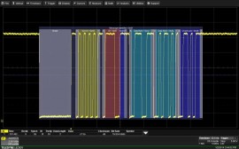
Intuitive, color-coded decode overlays ("D")
A transparent overlay with color-coding for specific portions of each protocol and the entire message frame makes it easy to understand your serial data information. Unlike other solutions, with protocol decode information away from the signal, our solution correlates the waveform and the protocol decode directly on the display. As the acquisition length is expanded or shortened, the decode overlay will adjust to show you just the right amount of information.
Interactive table summarizes results ("D")
Turn the oscilloscope into a protocol analyzer with a tabular display of decoded information. Customize the table to show only the data of interest and touch a message in the table to automatically zoom to it and display it on the screen. Export the table for offline analysis. Up to four different decoded signals of any type may be simultaneously displayed in the table.
Measure/graph tools for validation efficiency ("M")
Quickly validate cause and effect with automated timing measurements to or from an analog signal or another serial message. Make multiple measurements in a single long acquisition to quickly acquire statistics during corner-case testing. Serial (digital) data can be extracted to an analog value and graphed to monitor system performance over time, as if it was probed directly. Complete validation faster and gain better insight.
Powerful physical layer test ("P")
FlexRay eye diagram mask test overlays all the bits on FlexRay signal in an eye diagram with user-selected masks. Trigger on a specific Frame ID or range of IDs, or filter one long acquisition specific IDs, and show only those messages in the eye diagram. Supports SI Voting. Key timing parameters like Propagation Delay, Asymmetric Delay, Truncation and Jitter help you understand how signals propagate along the channel. Use statistics and histicons for deeper insight.
Eye diagrams ("P")
In addition to the capability described above, the standard Eye Diagram capability is also provided. Rapidly display an eye diagram of your packetized low-speed serial data signal without additional setup time. Use eye parameters to quantify system performance and apply a standard or custom mask to identify anomalies. Mask failures can be indicated and can force the scope into Stop mode.
| Trigger Capability | |
| Format | Hexadecimal or Binary for Frame ID Decimal for Cycle Count |
| Trigger Setup | Trigger on TSS (Start), Frame ID, Cycle Count, Symbols, and Errors |
| FRAME Setup | Specify Frame ID(s) in Hexadecimal or Binary with condition of <=, <, =, >, >=, <>, IN RANGE, OUT OF RANGE, or DON'T CARE Specify Cycle Count from 0 to 63 with condition of <=, <, =, >, >=, <>, IN RANGE, OUT OF RANGE, or DON'T CARE Specify Repetition Factor as 1, 2, 4, 8, 16, 32, or 64 Specify various Frame Qualifiers (Payload Preamble, Null Frame, Sync Frame, and Startup Frame) as 0, 1, or X (don't care) |
| DATA Setup | Hexadecimal # Data Bytes = 0 to 8. Data can be defined by nibble Binary Any combination of 0,1, or X for 1-64 bits Data pattern can be any length and can be set to start at any location in the up to 8 Byte/64 bit sequence |
| Error Setup | Trigger on any combination of the following errors: Frame Start Sequence (FSS) Error - triggers when the logic high time between the TSS and the first byte is too long Byte Start Sequence (BSS) Error - triggers anytime the BSS pattern is not seen between bytes where expected Frame End Sequence (FES) Error - triggers when the FS is not seen after the last byte Header CRC Error, Payload CRC Error (select Payload Channel A or B) |
| Symbol Trigger | Trigger on any combination of the following: Channel Idle Delimiter (CID) Symbol, Collision Avoidance Symbol (CAS) and/or Media Access Test Symbol (MTS), or Wakeup Pattern (WUP) |
| Bit Rates | 2.5, 5, or 10 Mb/s pre-defined nominal values, or user-defined nominal values in 1 Mb/s increments |
| Trigger Input | Any analog Channel or the EXT input |
| Decode + Search Capability | |
| Format | Hexadecimal, excepting Cycle Count (Decimal) |
| Decode Setup | Threshold definition required for High and Low levels. Default is to Absolute (in volts) amplitude. Select Channel (A or B) |
| Decode Input | Any analog Channel, Memory or Math trace, and any Digital trace |
| Number of Decodes | Up to 4 buses may be decoded at one time. In addition, zooms can be displayed (with decoded information) |
| Visual Aid | Color Coding for FRAME, TSS, CID, FSS, Frame Qualifiers, Slot ID, Payload Length, Header CRC, Cycle Count, Data, BSS, Payload CRC and FES Decode information is intelligently annotated based on timebase setting, and overlaid on acquired waveform |
| Table Configure, Export Table | Display 1 to 20 rows of decoded information for up to 4 different protocols or decodes in time order in a single table. Displayed information includes Index, Timestamp, and other various protocol-specific information. Table permits scrolling, touch to zoom, export to .csv file, and special display of long data or other patterns |
| Pattern Search | Search by Previous or Next Frame, Next ID (hexadecimal format), or Next Error Frame |